Search Colleges, Exams, Schools & more


Login
Force Between Two Parallel Current Carrying Conductors MCQ - Practice Questions with Answers
Edited By admin | Updated on Sep 25, 2023 25:23 PM | #NEET
Quick Facts
-

Force between two parallel current carrying infinite wires is considered one the most difficult concept.
-

32 Questions around this concept.
Solve by difficulty
 EASY
EASYIf the current is flowing clockwise in a circular coil, the direction of magnetic lines of force inside the coil is
The current is flowing in south direction along a power line. The direction of magnetic field above the power line (neglecting earth's field) is
Two long conductors, separated by a distance d carry current ${ } I_1$ and $I_2$ in the same direction. They exert a force F on each other Now the current in one of them is increased to two times and its direction is reversed. The distance is also increased to 3d. The new value of the force between them is
Two thin long, parallel wires, separated by a distance d carry a current of i A in the same direction. They will
Two long straight parallel wires, carrying (adjustable) currents I1 and I2, are kept at a distance d apart. If the force ‘F’ between the two wires is taken as ‘positive’ when the wires repel each other and ‘negative’ when the wires attract each other, the graph showing the dependence of ‘F’, on the product I1I2, would be :
Two concentric coils each of radius equal to $2 \pi \mathrm{~cm}$ are placed at right angles to each other. 3 A and 4 A are the currents flowing in each coil, respectively. The magnetic induction in $\mathrm{Wb} / \mathrm{m}^2$ at the centre of the coils will be:
$\left(\mu_0=4 \pi \times 10^{-7} \mathrm{~Wb} / \mathrm{A}-\mathrm{m}\right)$
Concepts Covered - 1
Force between two parallel current carrying infinite wires
Force between two parallel current carrying infinite wires-
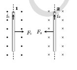
Let us take two long straight conductors carrying currents $i_{1 \text { and }} i_2$ placed parallel to each other at a distance 'a' from each other as shown in the figure -

Now, from the earlier concept which we have studied before, we can say that the conductor 2 experiences the some magnetic field at every point along its length due to the conductor 1. Because of this there will be some force acting on conductor 2 and the direction of magnetic force is indicated in the figure and it can be visualised by using the right-hand thumb rule.
Now, if we apply Ampere's circuital law on the first conductor then the magnitude of the magnetic field can be obtained as -
$$
B_1=\frac{\mu_0 I_1}{2 \pi a}
$$
Then the force on a segment of length $L$ of the conductor 2 due to the conductor 1 can be given as,
$$
F_{21}=I_2 L B_1=\frac{\mu_0 I_1 I_2}{2 \pi a} L
$$
Similarly, we can calculate the force exerted by the conductor 2 on the conductor 1 . We see that, the conductor 1 experiences the same force due to the conductor 2 but the direction of force is opposite. Thus we can say that,
$$
F_{21}=F_{12} \quad \text { (But the direction will be opposite.) }
$$
But if the direction of current flowing through the conductor is opposite in both the conductors then both the wire will repel each other.
Also, the magnitude of force acting per unit length can be given as -
$$
f_{12}=f_{21}=\frac{\mu_0 I_1 I_2}{2 \pi a}
$$
Study it with Videos
"Stay in the loop. Receive exam news, study resources, and expert advice!"
Get Answer to all your questions
Begin a career in Medical and Allied Sciences. Admissions Open for
Recognized as Category 1 University by UGC | Accredited with A+ Grade by NAAC | Scholarships available
Amity University Noida | Allied Health Sciences Admissions
ApplyRanked as India’s #1 Not for profit pvt. University by India Today
KCDSH- Krishnadevaraya Dental College & Sciences Admis 2026
ApplyRanked among the top Dental Colleges for 7 consecutive years by India Today poll
Max Institute of Allied and Paramedical Education (MIAPE)
ApplyGet Started With Your Healthcare Career. 2026 Admissions open.
Emversity Allied Health Programs
ApplyGet Job Ready in Healthcare | Employability-Focused Programs
Virohan Allied & Healthcare Programs
ApplyAllied & Healthcare programs | 20+ Partner Universities & Institutes | 98% placement record