Quick Facts
-

Logic Gates is considered one the most difficult concept.
-

41 Questions around this concept.
Solve by difficulty
 EASY
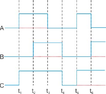
EASYThe figure shows a logic circuit with two inputs A and B and the output C. The voltage wave forms across A, B and C are as given. The logic circuit gate is:
Which logic gate is represented by the following combination of logic gates ?

The given electrical network is equivalent to:

Identify the gate and match A, B, Y in bracket to check.

Truth table for system of four NAND gates as shown in figure is

The following Figure shows a logic gate circuit with two inputs A and B and the output Y.The voltage waveforms of A,B and Y are given:

What is the output Y in the following circuit, when all the three inputs A, B, C are first 0 and then 1?

To get output 1 for the following circuit, the correct choice for the input is

Symbolic representation of four logic gate are shown as

Pick out which ones are for AND, NAND, and NOT gates, respectively
Concepts Covered - 1
Logic Gates-
In our day to day life,we come across many digital electronic devices. But do you know, for digital devices to function the way they do, a logic needs to be established between the input and output voltages. This is done by using a gate or a digital circuit that follows the logical relationship. They are called logic gates because they control the flow of information based on a certain logic.
Symbols are given to each logic gate and each logic gate has a truth table which displays all possible input-output combinations. So the truth tables help understand the behaviour of the logic gates. All these gates are made using semiconductor devices. The five most commonly used logic gates are:
- NOT
- AND
- OR
- NAND
- NOR
NOT Gate -
A NOT gate is also known as an inverter because it simply inverts the input signal. It is a simple gate with one input and one output. So, the output is ‘0’ when the input is ‘1’ and vice-versa.

A is input
Y is output
The truth table for a NOT gate is as follows:

AND Gate-
An AND gate has two or more inputs and a single output. In this gate, the output is 1(High) only when all the inputs are 1(High). The most commonly used symbol for an AND gate is as follows:

A and B are input
Y is output
And the truth table for the AND gate is as follows

OR Gate-
Like AND Gate, OR gate has also two or more inputs and one output. For this Gate, the logic is that the output would be 1 when at least one of the inputs is 1. It means when the output is high when any of the input is high. The commonly used symbol for an OR gate is as follows:

A and B are input
Y is output
Relation between input and output
And, the truth table for an OR gate is as follows:

NAND Gate-
A NAND gate is an arrangement of AND gate followed by a NOT gate. The output is 1 only when all inputs are NOT 1 Or the output is high when at least one of them is low. These are also called Universal gates. The commonly used symbol for a NAND gate is as follows:

A and B are input
Y is output
NOT + AND gate
And, the truth table for a NAND gate is as follows:

NOR Gate-
Like NAND Gate, NOR gate is also an arrangement of an OR gate followed by a NOT gate. In this the output is 1(High) only when all inputs are 0(Low). These are also called Universal gates. The commonly used symbol for a NOR gate is as follows:

A and B are input
Y is output
NOT + OR Gate
And the truth table for a NOR gate is as follows:

D'morgan's Theorem -
A and B are input.
1)
2)
3)
4)
Some Important relation -
Study it with Videos
 Logic Gates
"Stay in the loop. Receive exam news, study resources, and expert advice!"

Get Answer to all your questions
Articles
Download Careers360 App's
Regular exam updates, QnA, Predictors, College Applications & E-books now on your Mobile

300M+
Students

36,000+
Colleges

550+
Exams

1500+
E-Books

16000+
Certifications
