 EASY
EASYALLEN NEET Coaching
ApplyAce your NEET preparation with ALLEN Online Programs
Series LCR circuit is considered one the most difficult concept.
36 Questions around this concept.
In a LCR circuit capacitance is changed from C to 2C . For the resonant frequency to remain unchanged, the inductance should be changed from L to
In a series resonant LCR circuit, the voltage across R is 100 volts and R = 1 k with C = 2
. The resonant frequency
is 200 rad/s. At resonance the voltage across L is
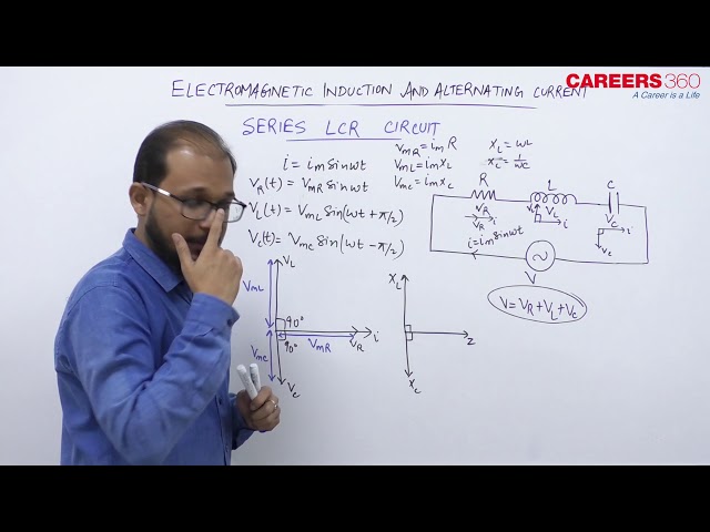
Series LCR circuit-

The Figure given above shows a circuit containing a capacitor ,resistor and inductor connected in series through an alternating / sinosoidal voltage source.
As they are in series so the same amount of current will flow in all the three circuit components and for the voltage, vector sum of potential drop across each component would be equal to the applied voltage.
Let 'i' be the amount of current in the circuit at any time and VL,VC and VR the potential drop across L,C and R respectively then
By all these we can draw phasor diagram as shown below -

One thing should be noticed that we have assumed that VL is greater than VC which makes i lags behind V. If VC > VL then i lead V. So as per our assumption, there resultant will be (VL -VC). So, from the above phasor diagram V will represent resultant of vectors VR and (VL -VC). So the equation become -
Here, Z is called Impedence of this circuit.
Now come to the phase angle. The phase angle for this case is given as -
Now from the equation of the phase angle three cases will arise. These three cases are -
(i) When,
then, tanφ is positive i.e. φ is positive and voltage leads the current i.
(ii) When
then, tanφ is negative i.e. φ is negative and voltage lags behind the current i.
(iii) When ,
then tanφ is zero i.e. φ is zero and voltage and current are in phase. This is called electrical resonance.
 Series LCR circuit
"Stay in the loop. Receive exam news, study resources, and expert advice!"

Ace your NEET preparation with ALLEN Online Programs

Admissions Open for multiple allied and health sciences programs across 5 campuses | Ranked #7 in India by NIRF, NAAC A++ Accredited

Enroll for NEET 2025 preparation program- Class XII Passed Students
Enrol in PW Vidyapeeth center for NEET coaching
Enrol in PACE IIT & Medical, Financial District, Hyd for JEE/NEET preparation

Know possible Govt/Private MBBS/BDS Colleges based on your NEET rank
Regular exam updates, QnA, Predictors, College Applications & E-books now on your Mobile
Students
Colleges
Exams
E-Books
Certifications
