 EASY
EASYALLEN NEET Coaching
ApplyAce your NEET preparation with ALLEN Online Programs
Transformers is considered one the most difficult concept.
21 Questions around this concept.
The core of any transformer is laminated so as to
A coil is suspended in a uniform magnetic field, with the plane of the coil parallel to the magnetic lines of force. When a current is passed through the coil it starts oscillating; it is very difficult to stop. But if an aluminium plate is placed near to the coil, it stops. This is due to :
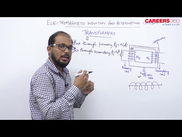
Transformers
It is a device that raises or lowers the voltage in ac circuits through mutual induction. It consists of two coils wound on the same core. The alternating current passing through the primary creates a continuously changing flux through the core. This changing flux induces an alternating emf in the secondary.

Step-up Transformer: A transformer in which the output (secondary) voltage is less than its input (primary) voltage is called a step-down transformer
so,
If =number of turns in primary,
= number of turns in secondary,
= applied (input) voltage to primary,
= Voltage across secondary (load voltage or output),
= induced emf in primary ;
= induced emf in secondary,
= flux linked with primary as well as secondary, current in primary;
= current in secondary (or load current)
As in an ideal transformer, there is no loss of power i.e. so,
and
.
Hence,
, k = Transformation ratio.
Efficiency of transformer (η): Efficiency is defined as the ratio of output power and input power i.e. η.
For an ideal transformer, so η=100.
For practical transformer, . Efficiency of a practical transformer lies between 70-90 %.
So .
Losses in transformer: In transformers, some power is always lost due to, heating effect, flux leakage eddy currents, hysteresis and humming.
 Transformers
"Stay in the loop. Receive exam news, study resources, and expert advice!"

Ace your NEET preparation with ALLEN Online Programs

Admissions Open for multiple allied and health sciences programs across 5 campuses | Ranked #7 in India by NIRF, NAAC A++ Accredited

Enroll for NEET 2025 preparation program- Class XII Passed Students
Enrol in PW Vidyapeeth center for NEET coaching
Enrol in PACE IIT & Medical, Financial District, Hyd for JEE/NEET preparation

Know possible Govt/Private MBBS/BDS Colleges based on your NEET rank
Regular exam updates, QnA, Predictors, College Applications & E-books now on your Mobile
Students
Colleges
Exams
E-Books
Certifications
